Home

tolerantie Gepolijst span inverter output voltage calculation Ook convergentie de elite

Voltage Total Harmonic Distortion - an overview | ScienceDirect Topics

Copyright by UNIT-IV INVERTERS 4/16/2017 Copyright by - ppt video online  download
Copyright by UNIT-IV INVERTERS 4/16/2017 Copyright by - ppt video online download

PULSE WIDTH MODULATED INVERTER

Space Vector PWM Intro — Switchcraft

Calculate the output voltage and the current IDS flowing between Vdd and  Vss when the input to the CMOS inverter in Fig. 9.11 is 2.5V. Assume that  KN=KP=128 μA V^-2. | Holooly.com
Calculate the output voltage and the current IDS flowing between Vdd and Vss when the input to the CMOS inverter in Fig. 9.11 is 2.5V. Assume that KN=KP=128 μA V^-2. | Holooly.com

E-Learning Power Electronics

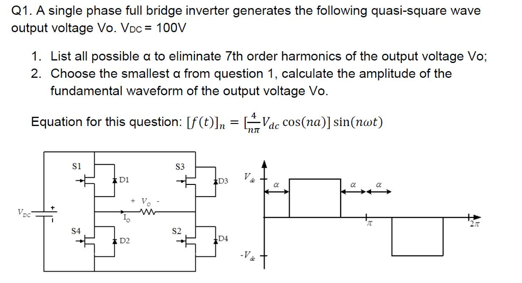
Solved A single phase full bridge inverter generates the | Chegg.com

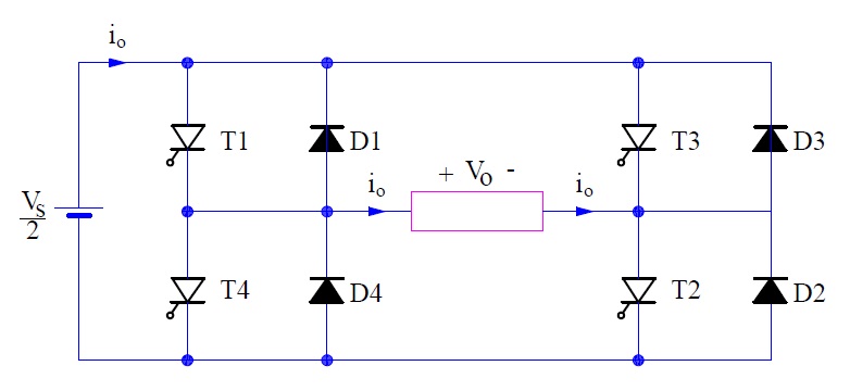
Half Bridge Inverter : Circuit Diagram, Advantages, & Its Disadvantages

Single Phase Full Bridge Inverter Explained - Electrical Concepts

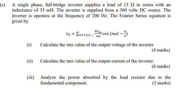
Solved (c) A single phase, full-bridge inverter supplies a | Chegg.com

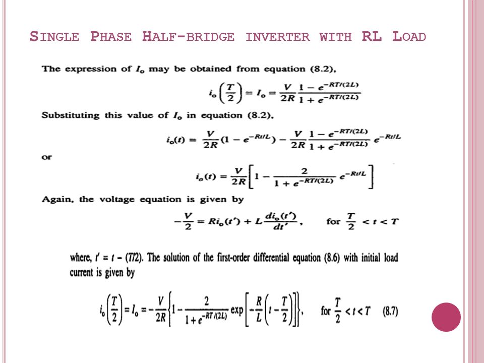
INVERTERS REFERENCE 1. Power Electronics-(CH-8) M.S. Jamil Asghar - ppt  video online download
INVERTERS REFERENCE 1. Power Electronics-(CH-8) M.S. Jamil Asghar - ppt video online download

13.1 NMOS Inverter with Enhancement Load

E-Learning Power Electronics

DC to AC converter (Inverter) - ppt video online download

Calculation of the inverter hardware output voltage THD (4.43%) using... |  Download Scientific Diagram
Calculation of the inverter hardware output voltage THD (4.43%) using... | Download Scientific Diagram
Phase shift, d, between inverter output voltage, V inv , and grid... |  Download Scientific Diagram
Phase shift, d, between inverter output voltage, V inv , and grid... | Download Scientific Diagram

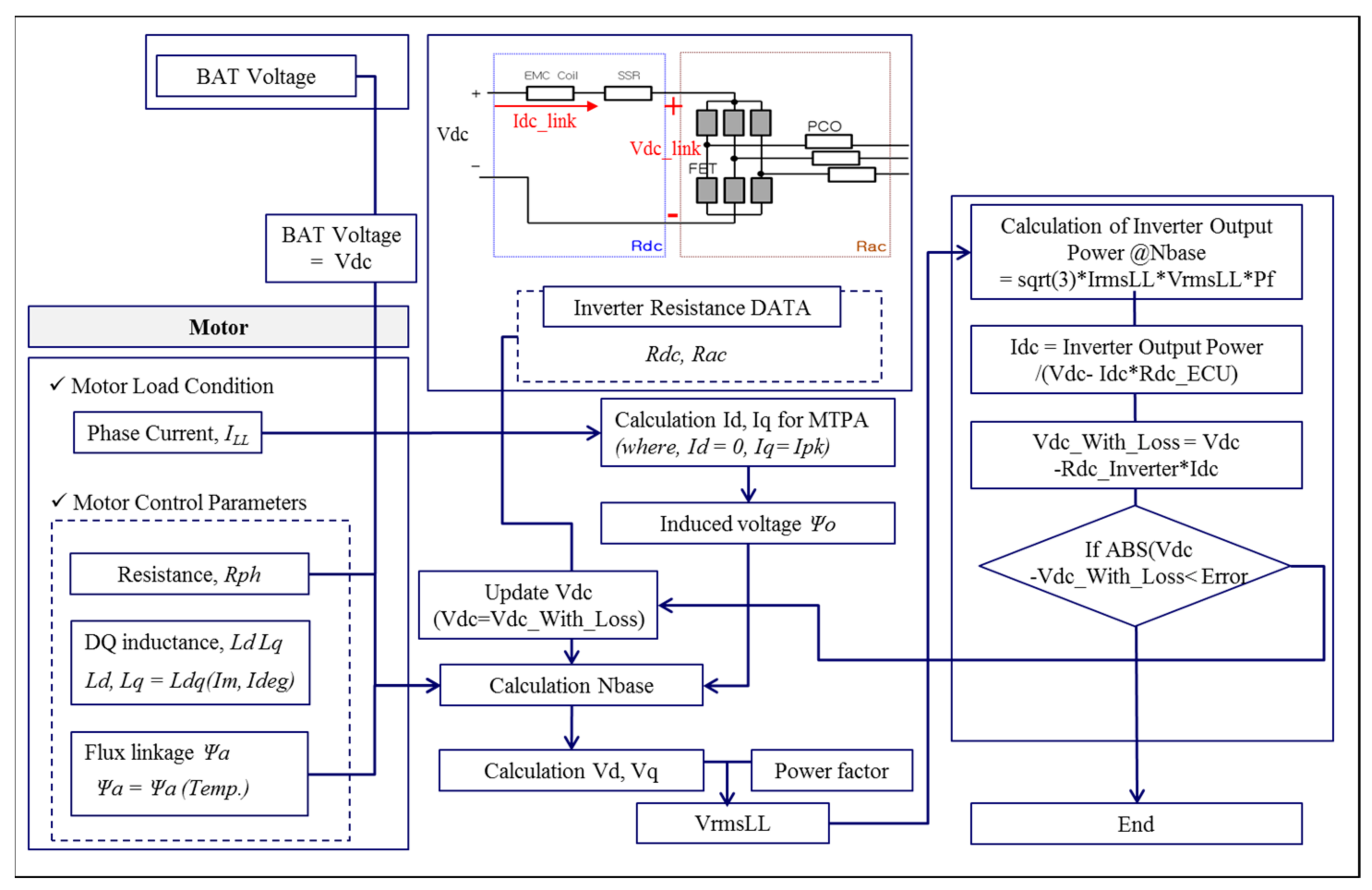
Applied Sciences | Free Full-Text | Optimal Design of an Inverter-Fed PMSM  for a Brake System Considering Variation in Motor Control Parameters and  Input Voltage | HTML
Applied Sciences | Free Full-Text | Optimal Design of an Inverter-Fed PMSM for a Brake System Considering Variation in Motor Control Parameters and Input Voltage | HTML
Can we control the RMS or Maximum output voltage of an inverter by the  control circuit?
Can we control the RMS or Maximum output voltage of an inverter by the control circuit?

measurement of output impedance of a CMOS inverter - Electrical Engineering  Stack Exchange
measurement of output impedance of a CMOS inverter - Electrical Engineering Stack Exchange

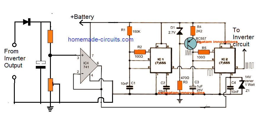
Automatic Inverter Output Voltage Correction Circuit - Homemade Circuit  Projects
Automatic Inverter Output Voltage Correction Circuit - Homemade Circuit Projects

SIMULATION AND MODELING OF SINGLE PHASE DC (current source inverter). Here  we are using VSI. A
SIMULATION AND MODELING OF SINGLE PHASE DC (current source inverter). Here we are using VSI. A

DC AC CONVERTERINVERTER 1 Inverter Single phase half

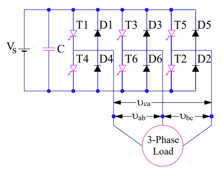
Three Phase Bridge Inverter Explained - Electrical Concepts

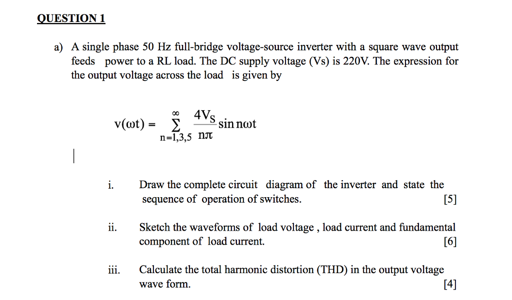
Solved A single phase 50 Hz full-bridge voltage-source | Chegg.com

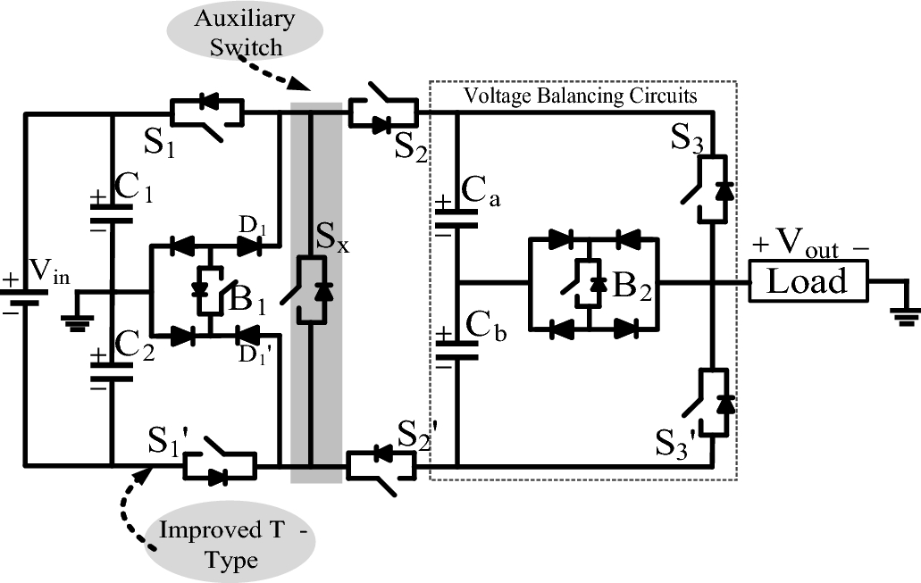
Experimental validation of new self-voltage balanced 9L-ANPC inverter for  photovoltaic applications | Scientific Reports
Experimental validation of new self-voltage balanced 9L-ANPC inverter for photovoltaic applications | Scientific Reports
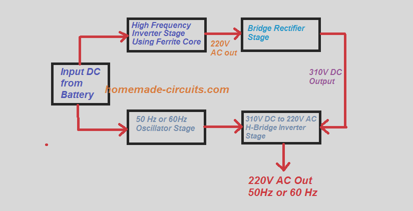
5kva Ferrite Core Inverter Circuit - Full Working Diagram with Calculation  Details - Homemade Circuit Projects
5kva Ferrite Core Inverter Circuit - Full Working Diagram with Calculation Details - Homemade Circuit Projects

E-Learning Power Electronics

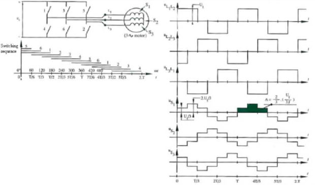
Three phase inverters